

EXPLORE THE STORY · 6 MIN READ
Why read this?
Understand how several equipment-position indications combine into one permissive, so a missing relay signal can be interpreted logically rather than blamed immediately on the relay.
Application in a substation
Circuit-breaker close-test interlocking. This branch checks disconnector-open auxiliary indications before the displayed condition relay K101 can energise; it is only one part of the complete closing scheme.
What condition is checked?
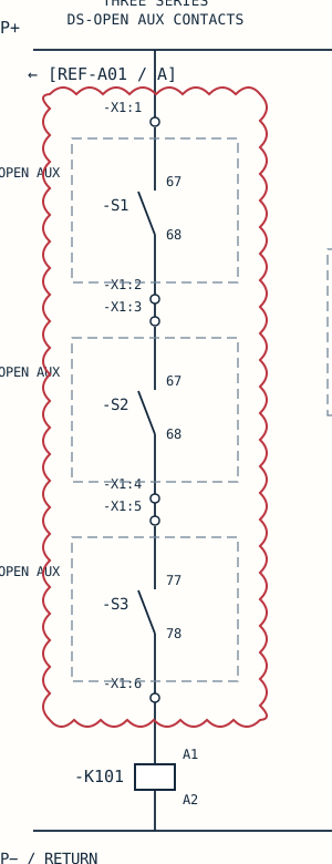
S1, S2 and S3 must all conduct. Here, their closed auxiliary-contact states represent the required disconnector-open indications. Supply, return, wiring and coil must also be healthy.
What changes when the condition is lost?
If one contact opens, this branch loses continuity and cannot energise K101. That identifies a missing electrical condition; it does not by itself identify the physical device position or the faulty component.
Where else is the same principle used?
Comparable logic appears in breaker racking-position permissives, earthing-switch position interlocks and maintenance-test permissives. The required open/closed positions differ by design; do not transfer this particular three-contact arrangement to another bay.
What you should understand afterwards
You should be able to trace the permissive and explain why a closed auxiliary contact can indicate an open disconnector.
Substation use case: a close-test permissive that does not pick up
What this circuit is for: the three series contacts feed relay K101, representing a circuit-breaker (CB) close-test interlock condition. Each contact is operated by a disconnector (DS) mechanism and represents its open-position condition. The contacts are labelled S1, S2 and S3; their equipment groups are DS1, DS2 and DS3.
Important distinction: a closed auxiliary contact can indicate that the main disconnector is open. “Contact closed” and “disconnector closed” are different statements.
A realistic teaching scenario
During an authorised commissioning test, the expected close-test permissive is absent. Two disconnector-open auxiliary contacts provide continuity, but the third does not. With that one contact open, the displayed series branch is interrupted and K101 cannot energise through this path, even if the other two contacts are closed.
This helps an engineer separate a missing position indication from a relay or wiring problem. An open auxiliary contact alone does not establish the physical disconnector position: the device state, auxiliary-switch mechanism, terminal wiring, control supply and return are separate pieces of evidence.
Follow the logic
- Find the P+ supply and follow the wire through S1, S2 and S3.
- Match each contact to its DS-open equipment label and numbered terminals.
- Follow the path into coil terminal A1 of K101 and from A2 to P−.
- Notice that there is no parallel bypass around the three contacts in this branch. Every contact must conduct for this displayed coil path to be complete.
Why learn this: it makes an interlock failure easier to understand and helps distinguish primary equipment position from its electrical indication. It also prevents the mistaken conclusion that three closed auxiliary contacts mean three closed disconnectors.
Scope: this is an illustrative scenario, not a reported incident or an operating procedure. K101 is one condition relay; its energisation does not prove that every breaker-closing interlock is satisfied. Do not bypass interlocks or treat an indication as proof of isolation.
Why three contacts must agree before a relay can operate
This example explains a permissive chain: three position contacts are connected in series before relay K101. All three contacts must be closed for this branch to conduct. The drawing alone does not establish which real equipment position is safe.
What to follow
Start at P+, follow S1, S2 and S3 down to coil K101, then follow A2 to P−. One open contact breaks the path. A complete path also requires a healthy supply, wiring and coil.
Read the symbols first
- P+ / P−: DC control supply and return.
- S: position-operated contact; PS: pressure switch; K: relay; X: terminal strip.
- A1 / A2: relay coil terminals.
- NO / NC: normally open / normally closed, in the drawing’s stated reference condition. These labels do not prove the live equipment state.
- 13–14, 21–22: contact terminal pairs. The lists below the coils identify associated relay contacts.
- REF: continuation to another drawing location. Check the reference register for availability.
TECHNICAL ARTICLE · SOURCE-BASED LEARNING EXAMPLE
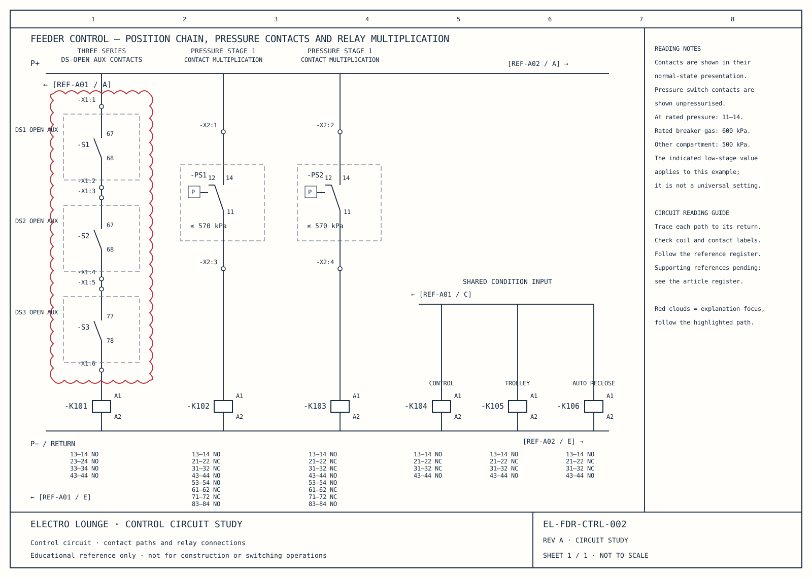
Swipe or scroll sideways to read the full sheet. Contact and terminal relationships remain visible.
Follow the left-hand branch on the drawing. Three position contacts appear one after another before the control-relay coil. This is the important visual clue: the path has no parallel bypass around any of those three contacts.
Each contact sits inside a separate dashed equipment boundary. The terminal markers show where the circuit enters and leaves that equipment. Contact terminal numbers and terminal-strip positions perform different jobs: one identifies the switching element, while the other identifies a wiring connection.
For the illustrated relay path to be continuous, every series contact must provide continuity. A single open contact interrupts that branch. This is a circuit-reading conclusion, not proof of the physical state of an entire bay. A healthy supply, intact wiring, a suitable return and a healthy coil are also required.
The red cloud selects the three-contact chain. Read down from P+ through the connection points, then locate A1 and A2 at the relay coil and trace the return. Cross-references are links to other drawing information; they are not additional electrical components.
Follow the drawing references
The annotated sheet is one part of a larger control circuit. Use this register to distinguish included material from the supporting sheets still to be redrawn.
| Neutral reference | What to follow | Included here |
|---|---|---|
| EL-FDR-CTRL-002 | Series position chain, pressure channels and three shared-input relays | Full selected-sheet redraw |
| REF-A01 / A, C, E | Incoming positive rail, common condition input and return | Supporting sheet redraw pending |
| REF-A02 / A, E | Supply continuation and connected control logic | Supporting sheet redraw pending |
| K101–K106 / R references | Associated relay contacts on other control and signalling sheets | Contact inventory included; destination-sheet redraws pending |
One handwritten destination reference cannot yet be read confidently. It remains unresolved rather than being assigned a guessed destination.
Diagram: Electro Lounge educational redraw. Supporting references follow.