

EXPLORE THE STORY · 4 MIN READ
Why read this?
Understand how one pressure-derived condition reaches several control destinations, and why several relay contacts do not mean several independent pressure measurements.
Application in a substation
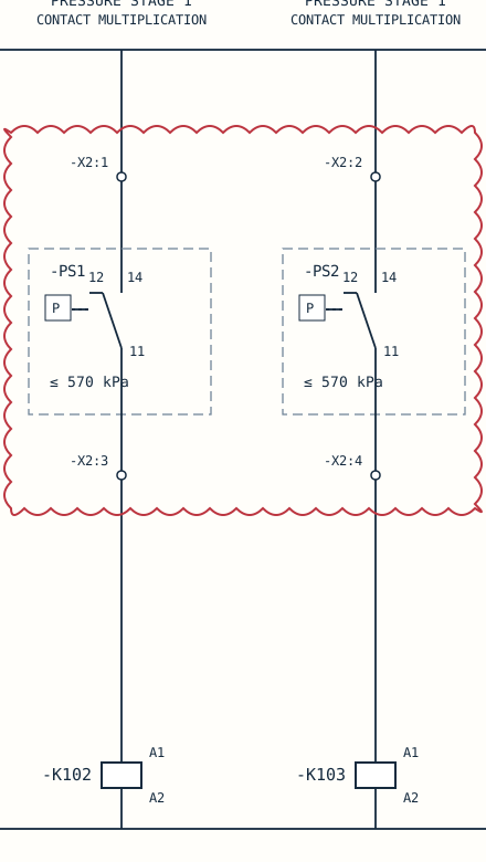
Gas-insulated switchgear pressure supervision associated with breaker close lockout. The displayed PS1 and PS2 channels operate intermediate relays K102 and K103 so their conditions can be represented by additional contacts elsewhere.
What condition is checked?
Each relay depends on its own pressure-operated changeover contact providing the displayed conducting path, plus a healthy control supply, return and coil. Interpret pressure direction and thresholds using the stated contact convention and equipment documentation.
What changes when the condition is lost?
When a pressure switch changes state, the relay path can change and its associated contacts change with it. The downstream close-lockout result must be traced on the referenced sheets; it is not established by this sheet alone.
Where else is the same principle used?
Comparable interface arrangements are used for transformer temperature alarms, mechanism pressure supervision and oil-level indications. Sensor type, contact state, threshold and required fail-safe behaviour must be checked for each design.
What you should understand afterwards
You should be able to distinguish the measured condition, the interface relay and the downstream function, without treating contact multiplication as sensor redundancy.
How a pressure condition becomes several electrical signals
This example shows pressure switches PS1 and PS2 operating intermediate relays K102 and K103. The relays make the pressure-related condition available to other control functions through their contacts.
What to follow
Follow each pressure-switch branch separately from P+ through the selected contact to its relay coil and return. Several relay contacts can represent one measurement; they do not create independent pressure sensors.
Read the symbols first
- P+ / P−: DC control supply and return.
- S: position-operated contact; PS: pressure switch; K: relay; X: terminal strip.
- A1 / A2: relay coil terminals.
- NO / NC: normally open / normally closed, in the drawing’s stated reference condition. These labels do not prove the live equipment state.
- 13–14, 21–22: contact terminal pairs. The lists below the coils identify associated relay contacts.
- REF: continuation to another drawing location. Check the reference register for availability.
TECHNICAL ARTICLE · SOURCE-BASED LEARNING EXAMPLE
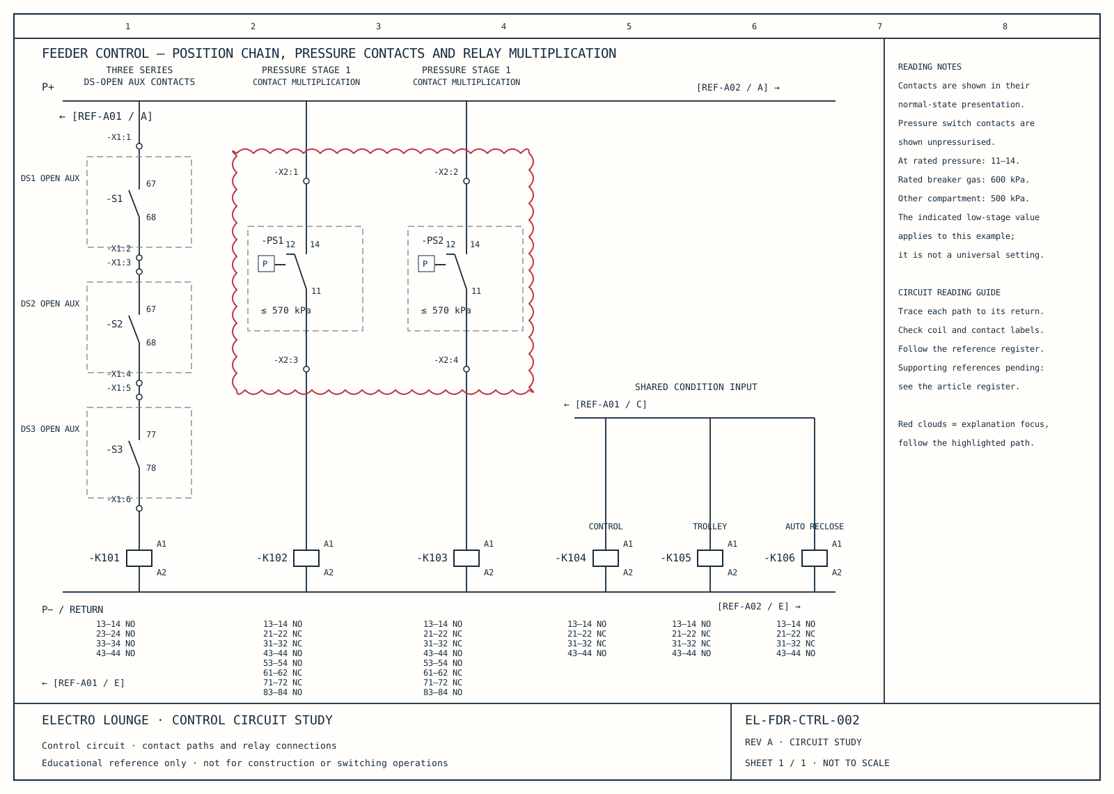
Swipe or scroll sideways to read the full sheet. Contact and terminal relationships remain visible.
The middle two branches each contain a pressure-operated changeover contact and a control-relay coil. They are separate channels sharing the displayed supply and return rails. Their role here is contact multiplication for a breaker-close-related function.
A changeover contact has a common terminal and two alternative throws. Read the normal-state convention in the notes before interpreting the contact. The drawing notes distinguish the unpressurised presentation from the contact relationship at rated pressure.
The intermediate relay lets one pressure-derived condition be represented by several associated relay contacts elsewhere. Those contacts can feed different destinations. They do not constitute several independent pressure measurements: one initiating channel still supports the multiplied indications.
The low-stage value printed beside these branches belongs to this particular reference scheme. It must not be treated as a general GIS setting or transferred to other equipment. The cloud highlights the contact selection and terminal relationships being discussed.
Follow the drawing references
The annotated sheet is one part of a larger control circuit. Use this register to distinguish included material from the supporting sheets still to be redrawn.
| Neutral reference | What to follow | Included here |
|---|---|---|
| EL-FDR-CTRL-002 | Series position chain, pressure channels and three shared-input relays | Full selected-sheet redraw |
| REF-A01 / A, C, E | Incoming positive rail, common condition input and return | Supporting sheet redraw pending |
| REF-A02 / A, E | Supply continuation and connected control logic | Supporting sheet redraw pending |
| K101–K106 / R references | Associated relay contacts on other control and signalling sheets | Contact inventory included; destination-sheet redraws pending |
One handwritten destination reference cannot yet be read confidently. It remains unresolved rather than being assigned a guessed destination.
Diagram: Electro Lounge educational redraw. Supporting references follow.