

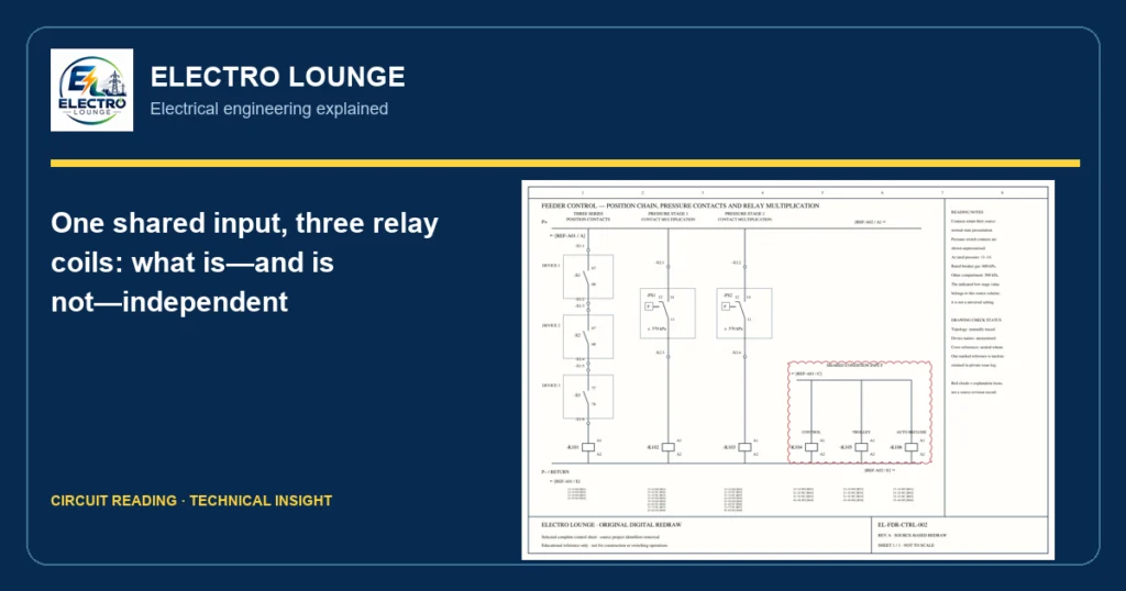
EXPLORE THE STORY · 4 MIN READ
Why read this?
Understand the difference between distributing one condition and independently verifying it. This helps explain why several indications can disappear together.
Application in a substation
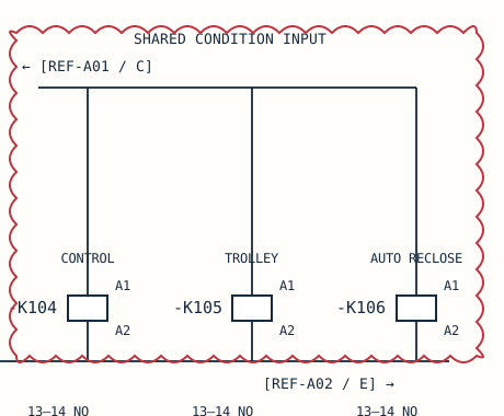
One incoming condition signal is distributed to three interface relay coils, K104–K106. The associated contacts allow the same initiating condition to be used in separate control functions.
What condition is checked?
The common input must be available and each branch must have its own intact coil path to the shared return. The origin and complete logic of that input require the referenced drawing information.
What changes when the condition is lost?
Loss of the common input can affect all three coils. A fault confined to one branch can affect only that branch, depending on upstream protection and the fault type. Three coils therefore do not establish three independent confirmations.
Where else is the same principle used?
Comparable arrangements distribute a permissive to breaker-control circuits, an indication to a supervisory system and a condition to an automatic function. These are examples of the same principle, not additional destinations established by this drawing.
What you should understand afterwards
You should be able to distinguish a shared dependency from a local branch problem and avoid mistaking multiple relays for independent evidence.
Why three relays can still depend on one signal
This example shows one condition input branching to coils K104, K105 and K106. It distributes one condition to several uses, rather than providing three independent confirmations.
What to follow
Start at the shared horizontal input line, follow each vertical branch to A1, then trace A2 to the return. The input and return are common dependencies.
Read the symbols first
- P+ / P−: DC control supply and return.
- S: position-operated contact; PS: pressure switch; K: relay; X: terminal strip.
- A1 / A2: relay coil terminals.
- NO / NC: normally open / normally closed, in the drawing’s stated reference condition. These labels do not prove the live equipment state.
- 13–14, 21–22: contact terminal pairs. The lists below the coils identify associated relay contacts.
- REF: continuation to another drawing location. Check the reference register for availability.
TECHNICAL ARTICLE · SOURCE-BASED LEARNING EXAMPLE
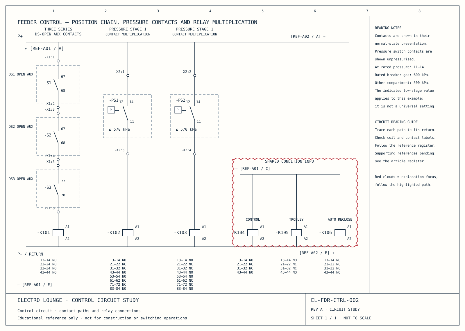
Swipe or scroll sideways to read the full sheet. Contact and terminal relationships remain visible.
The right-hand group shows one incoming condition signal branching to three relay coils. Their lower connections meet the displayed return. This makes the common input easy to see without inventing a separate source for each coil.
The coil labels identify each relay. A1 and A2 identify coil terminals. Each relay has associated contact references below it, allowing its effect to be followed on other sheets. The labelled destinations distinguish different uses of the same initiating condition.
Three coils do not automatically mean three independent confirmations. A loss of the common input can affect all of them. Conversely, a fault in one coil or downstream contact does not by itself prove the common input is absent. Diagnosis needs evidence at the relevant connection points.
The cloud selects the common feed and the three branches. Compare this arrangement with the series chain on the left: series contacts combine conditions along one path, whereas this section distributes a shared input to separate relay coils.
Follow the drawing references
The annotated sheet is one part of a larger control circuit. Use this register to distinguish included material from the supporting sheets still to be redrawn.
| Neutral reference | What to follow | Included here |
|---|---|---|
| EL-FDR-CTRL-002 | Series position chain, pressure channels and three shared-input relays | Full selected-sheet redraw |
| REF-A01 / A, C, E | Incoming positive rail, common condition input and return | Supporting sheet redraw pending |
| REF-A02 / A, E | Supply continuation and connected control logic | Supporting sheet redraw pending |
| K101–K106 / R references | Associated relay contacts on other control and signalling sheets | Contact inventory included; destination-sheet redraws pending |
One handwritten destination reference cannot yet be read confidently. It remains unresolved rather than being assigned a guessed destination.
Diagram: Electro Lounge educational redraw. Supporting references follow.