

EXPLORE THE STORY · 5 MIN READ

Why read this? Learn what holds an overhead conductor in tension, where electrical insulation is needed, and how to identify the fittings in an EHV line assembly.
Look up at an overhead power line and you will see more than wires and towers. Between the conductor and the structure is a carefully arranged chain of insulators and metal fittings. Each part has a job. Understanding those jobs is a useful first step toward reading transmission-line drawings.
In this lesson, we explore a tension insulator assembly: the arrangement that anchors a tensioned conductor while keeping it electrically separated from its supporting structure.
What is it used for?
A conductor pulls on its attachment points, much like a stretched rope pulls on its anchors. A tension assembly transfers that mechanical pull into a tower, pole or terminal structure. At the same time, its insulators provide the electrical separation needed between the energized hardware and the structure.
You will encounter tension arrangements at line terminations, at angle structures where the route changes direction, and at other locations where the design anchors a conductor section. The exact arrangement depends on the line design.
Explore the assembly in 3D
Tap or click a part to learn its name and purpose. Drag to rotate and use the wheel or a two-finger pinch to zoom. The part list helps you select small fittings. Switch to the full assembly to see the insulator strings, or focus on the yokes and clamps for a closer look.
THE ENGINEERING CORNER
Follow the pull, then follow the current
1. The mechanical load path
Imagine following the conductor’s pull toward the tower. It passes through the dead-end clamp, connecting links, yoke plates, insulator strings and attachment fittings to the supporting structure. The exact order and branching depend on the assembly. A fitting can be small and still be essential to this chain.
2. The electrical current path
The intended current path stays with the conductors and their electrical connections. Where conductor sections are mechanically terminated on opposite sides of a structure, a jumper can connect them electrically. Normal line current is not intended to pass through the insulator strings into the tower.
A dead end is a mechanical termination; it does not necessarily mean that electricity stops there. This distinction makes many line drawings much easier to understand.
Meet the main parts
- Insulator strings: provide mechanical support and electrical separation. The model uses two parallel strings. Their quantity and rating are design choices; two strings do not automatically prove that one can be removed safely.
- Yoke plates: connect multiple attachment points and organize the load path across the assembly. Rotate the model to see how the connections branch.
- Clevises, hinges and pins: join neighboring fittings and provide articulated connections so the assembly can align. Pins require their specified retaining arrangements.
- Extension links: provide the required connection length and geometry. An adjustable link offers specified pin positions; its holes are not arbitrary adjustment or lifting points.
- Compression dead-end clamps: grip and terminate the conductors. Their jumper terminals provide electrical connection points. The conductor wires and jumper wires are not included in this model.
- Arcing horn and ring: form part of the electrical-field or arc-control arrangement at the insulator ends. Their shape and position have electrical purposes; they are not structural handles.
THE ENGINEERING CORNER
Four conductors does not mean four phases
The four clamps represent attachment points for four sub-conductors in a bundle. A bundle can form one electrical phase. Keep conductor count, insulator-string count and phase count separate when reading a drawing.
TRY IT YOURSELF
A short exercise for your next drawing review
- Find the structure end and the conductor end.
- Trace one continuous mechanical connection between them.
- Find where electrical insulation interrupts the metal connection toward the structure.
- Locate the jumper terminal and explain where a jumper would continue the circuit.
- Identify a detail that the drawing or model does not establish.
If you can explain these five points, you are reading the assembly as a working system rather than memorizing a list of parts.
What this learning model can tell you
The viewer helps you recognize components, understand connections and ask better questions. It uses generic names and contains estimated contours, simplified fittings and schematic insulators. It does not verify load ratings, electrical clearances or installation methods. Use approved project documents and qualified engineering review for real work; no lifting capacity is assigned to any hole in this model.
Sources & further reading
- OSHA — electrical-power terminology, including line insulators ↗ osha.gov
- Transmission-tower photograph — source and photographer credit ↗ commons.wikimedia.org
- Photograph reuse license — CC BY 2.0 ↗ creativecommons.org
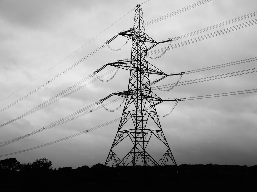
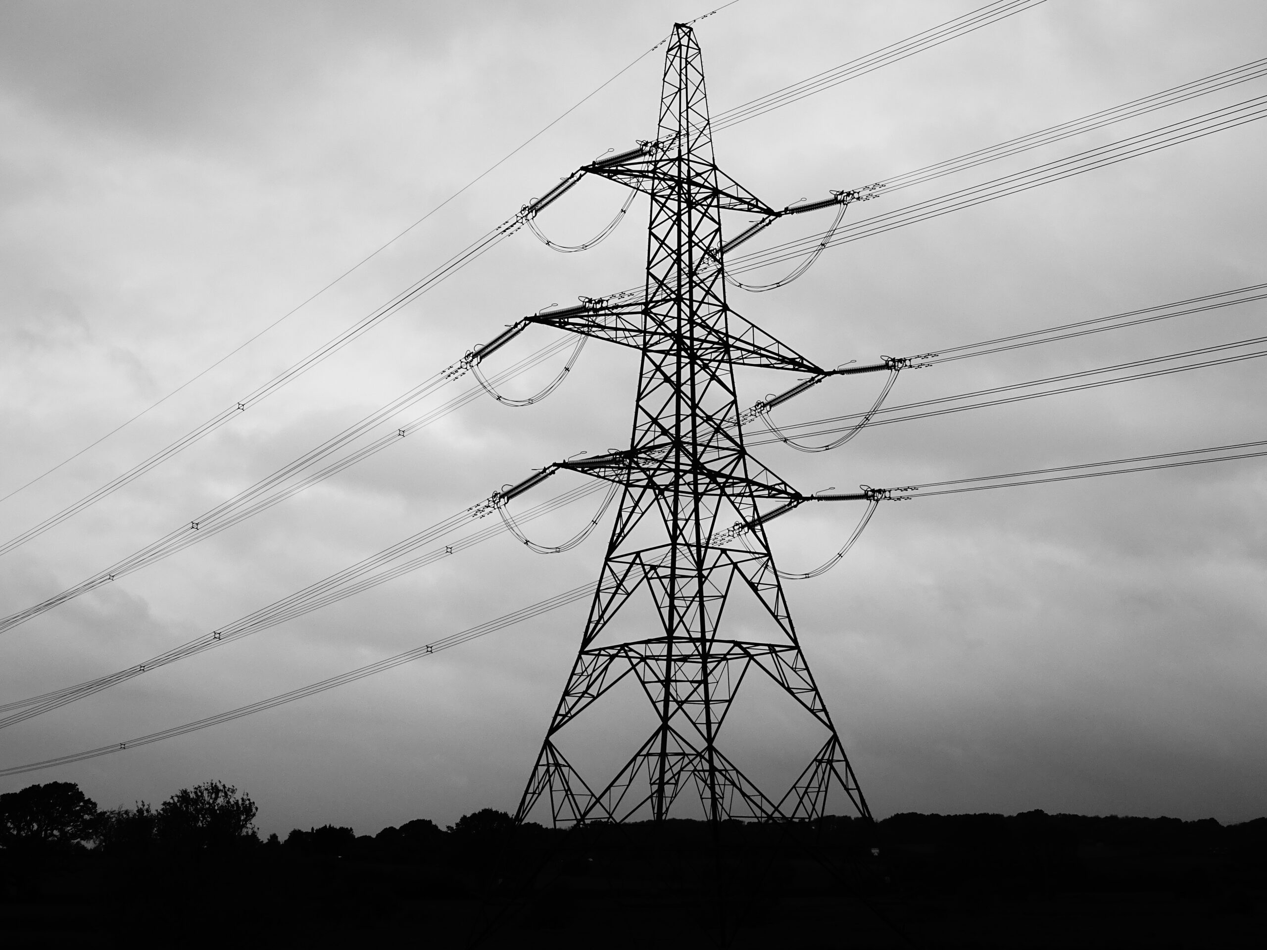
The photograph illustrates general principles and does not identify the modeled product.